
3. Running an optimisation
Setting optimisation parameters
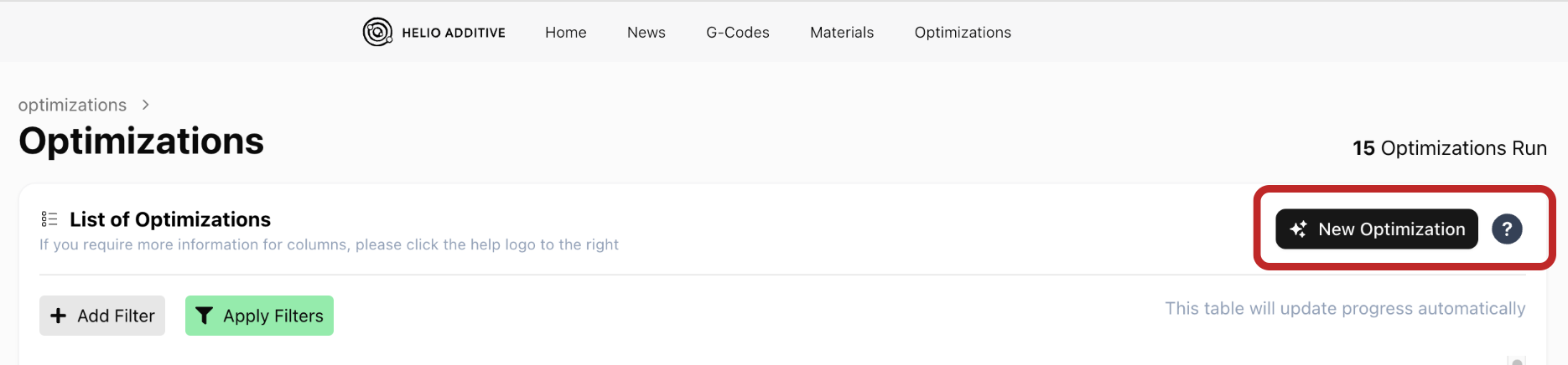
Section titled “Setting optimisation parameters”3.1 After uploading the G-code, click on the “Optimizations” tab to enter the optimization interface.

3.2 Click “New Optimization” to start setting up a new optimization.
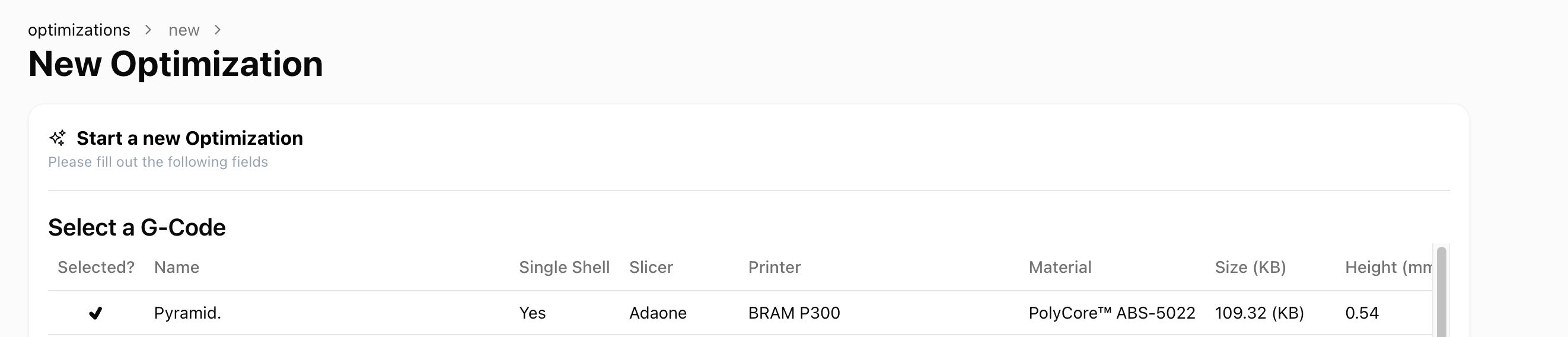
3.3 Select your G-code by clicking on it. Once it’s selected, a checkmark appear next to the selected G-code.
3.4 Set the Optimisation parameters:
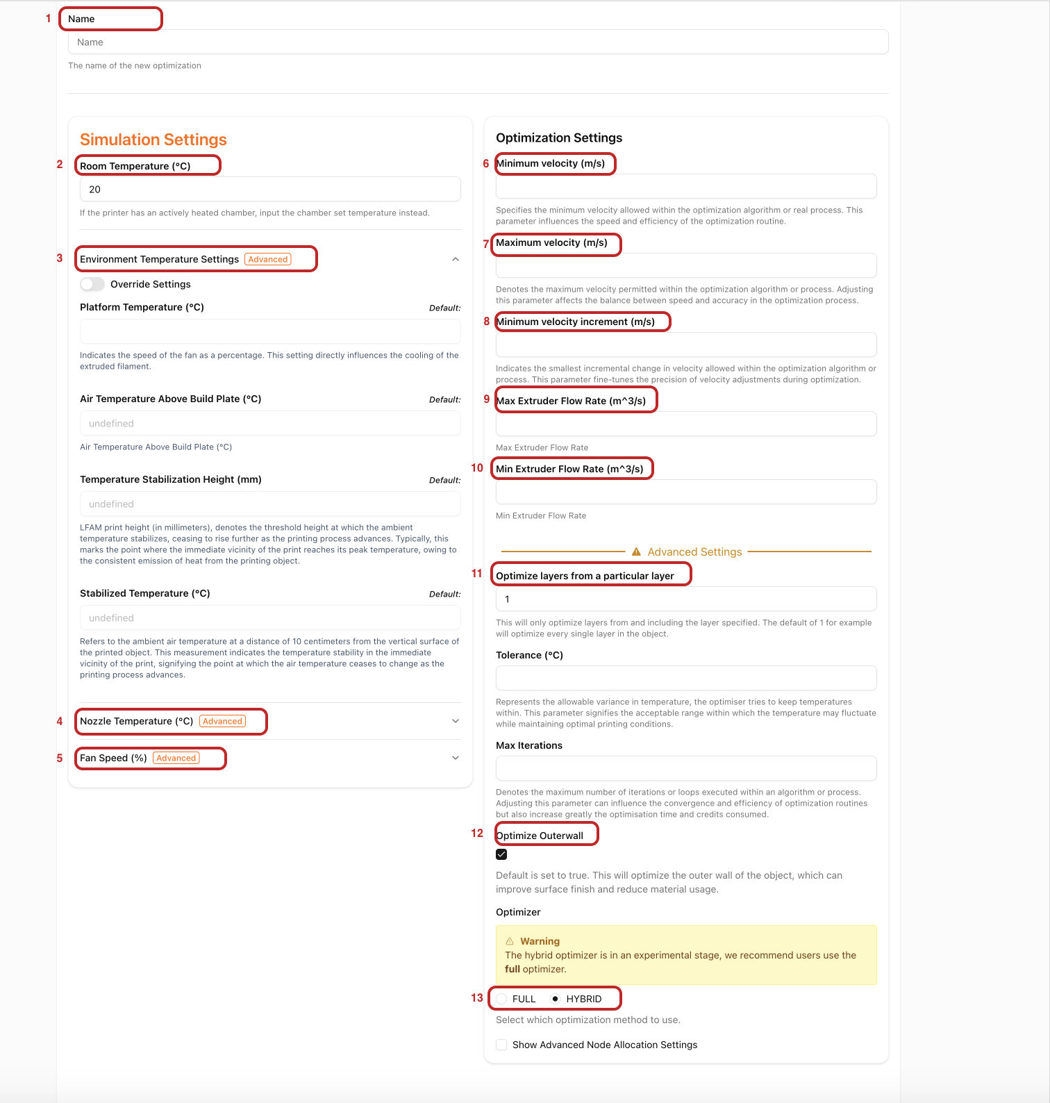
1. Optimization Name
:A default name is automatically set based on the name of the G-code you selected for optimisation2. Room temperature
:Simply your ambient environment temperature-
If your printer has an actively heated chamber, enter the chamber temperature you’ve set.
-
If your printer does not have an actively-heated chamber, enter your ambient air temperature
3. Environment Temperature settings These are temperature settings based on your set-up. The defaults are predetermined as follows:
- Platform temperature: Set in the G-code upload page.
- Air Temperature Above the Build Plate
- Temperature Stabilisation Height
- Stabilised Temperature
4. Nozzle Temperature (℃): If you want to override the nozzle temperature set in the G-code upload page, enter the new nozzle temperature here. The optimization process will use this new nozzle temperature. If you do not need to redefine the nozzle temperature, leave this field blank, and the optimization will use the original nozzle temperature by default.
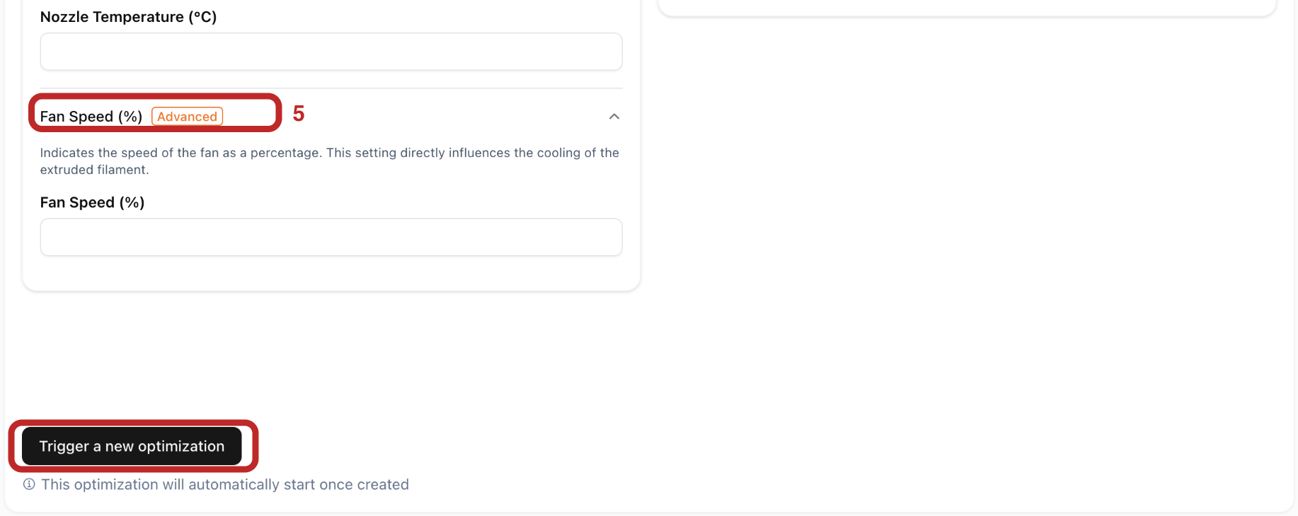
5. Fan speed (%): Constant fan speed of your print.
6. Minimum Print Speed (m/s): The minimum print speed that the printer can achieve.
7. Maximum Print Speed (m/s): Your printer’s maximum speed.
8. Minimum Optimization Speed Increment (m/s): The minimum speed increment for adjustments during optimization. If there are no extremely small sections in the print structure, the default value (0.01) should work great.
9. Max extruder flow rate (m³/s): The highest rate (in m³/s) at which material can be reliably extruded through your nozzle. This directly limits the maximum print speed written into your optimized G-code. Default values are pre-set based on your selected printer, but if you have more accurate measured values, it’s recommended to override the default for best results.
10. Min extruder flow rate (m³/s): The minimum rate at which material can be extruded through the nozzle.
11. Optimise from a particular layer: Allows you to specify the layer from which the optimiser should start adjusting speeds in your object.
This feature is useful when you want to keep the speeds for the first few layers unchanged.
12.Optimise Outer Wall Allows you to choose whether to optimise the outer wall of your object or not. The default is set to true. If surface quality finish of your obeject is the most important thing, unselect this/set to false. Note that this might include trade offs to thermal quality index.
13. Full vs Hybrid Optimiser: Choose the optimisation strategy to use.
-
Full optimisation strategy : Simulates each layer sequentially with each iteration before optimisation. You can control the optimisation detail using the node allocation settings under “Reduction strategy”
-
Hybrid optimiser : Breaks simulations into segments that start and stop at specific points. It then optimises different parts of the object independently, enabling faster results while optimising every layer
Advanced Settings: Usually, no adjustments are needed; the default values should be sufficient. If they need adjusting, the Helio Additve team will advise you on how to best set them.
After verifying that all the parameters are correct, click the “Trigger a new optimization” button in the bottom left corner to start the optimization process.
After triggering the simulation, monitor the status/progress in the optimization list.
Optimisation statuses
Section titled “Optimisation statuses”Simulations & Optimizations all run in the cloud, and can sometimes be long running processes, as such we provide status updates to help you to understand the state and progress of your simulation or optimization.
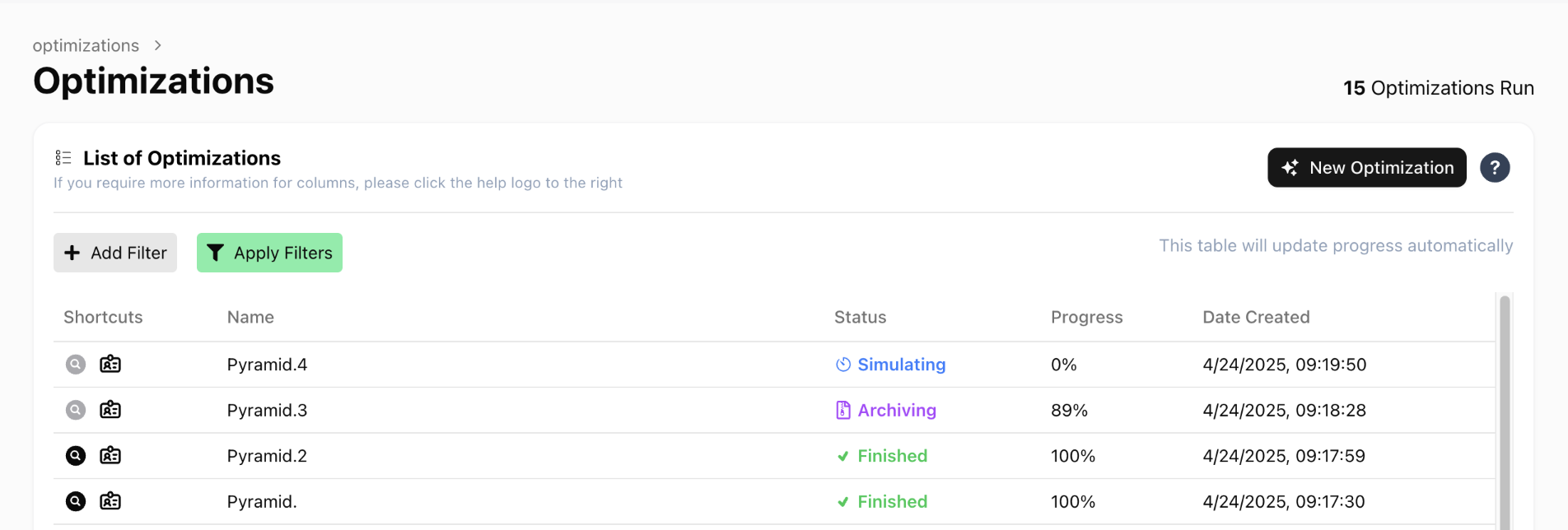
- Pending - Indicates we have received the request to simulate, and we are provisioning resources for the simulation to run.
- Initializing - The simulation is preparing all required files for the simulation to start.
- Simulating - The simulation is running.
- Archiving - The core simulation has finished, we are now doing a few post-processing steps and data exports to make the data available for you to download.
- Finished - The simulation has completely finished.
- Failed - The simulation has failed.
- Stopped - The simulation has been stopped externally.
Appendix
Section titled “Appendix”How the default temperature conditions are calculated
Section titled “How the default temperature conditions are calculated”Air Temperature Above the Build Plate
Room temperature here refers to the ambient temperature in your printing environment. If you are using a heated chamber, your room temperature will be your chamber heat setting.
| Bed heating | With chamber | With Heated Chamber | Air Temperature Above the Build Plate |
|---|---|---|---|
| Yes | Yes | No | (Platform temperature + *Room temperature) / 2 |
| No | Yes | No | *Room temperature |
| Yes | Yes | No | *Room temperature |
| No | No | No | (Platform temperature + *Room temperature) / 2 |
| Yes | No | No | (Platform temperature + *Room temperature) / 2 |
Temperature stabilisation height
As printing progresses, the room temperature may gradually increase until it becomes stable. The height (in mm) at which the temperature stabilises is the layer threshold.
| Bed heating | With chamber | With Heated Chamber | Temperature stabilisation height(mm) |
|---|---|---|---|
| Yes | Yes | No | 20 |
| No | Yes | No | 40 |
| Yes | Yes | No | 80 |
| No | No | No | 20 |
| Yes | No | No | 20 |
Stabilized temperature
As printing progresses, the room temperature may gradually increase until it becomes stable. This stable temperature 10cm from the vertical surface of the print is the object proximity temperature.
| Bed heating | With chamber | With Heated Chamber | Stabilized temperature (°c) |
|---|---|---|---|
| Yes | No | No | Room temperature + 20 |
| No | Yes | No | Room temperature + 15 |
| No | No | No | Room temperature + 10 |
| Yes | No | No | Room temperature + 15 |
| Yes | No | Yes | Room temperature |
If you have more accurate, measured values, you can toggle on ‘Override Settings’ to input them manually. You’ll need to fill in all the settings once override is on.
How does Dragon optimise my G-code?
Section titled “How does Dragon optimise my G-code?”Dragon optimises your G-code by adjusting extrusion speeds to ensure thermal conditions are met for your specific printer, material and object. While retraction and travel speeds themselves aren’t modified, since they’re assumed to be already tuned for your setup, Dragon does account for their impact on thermal conditions. This means cooling delays, air movement, and other non-extrusion effects are factored into the simulation and optimisation to improve accuracy.